Custom Membrane Keypad Switch For Better Control

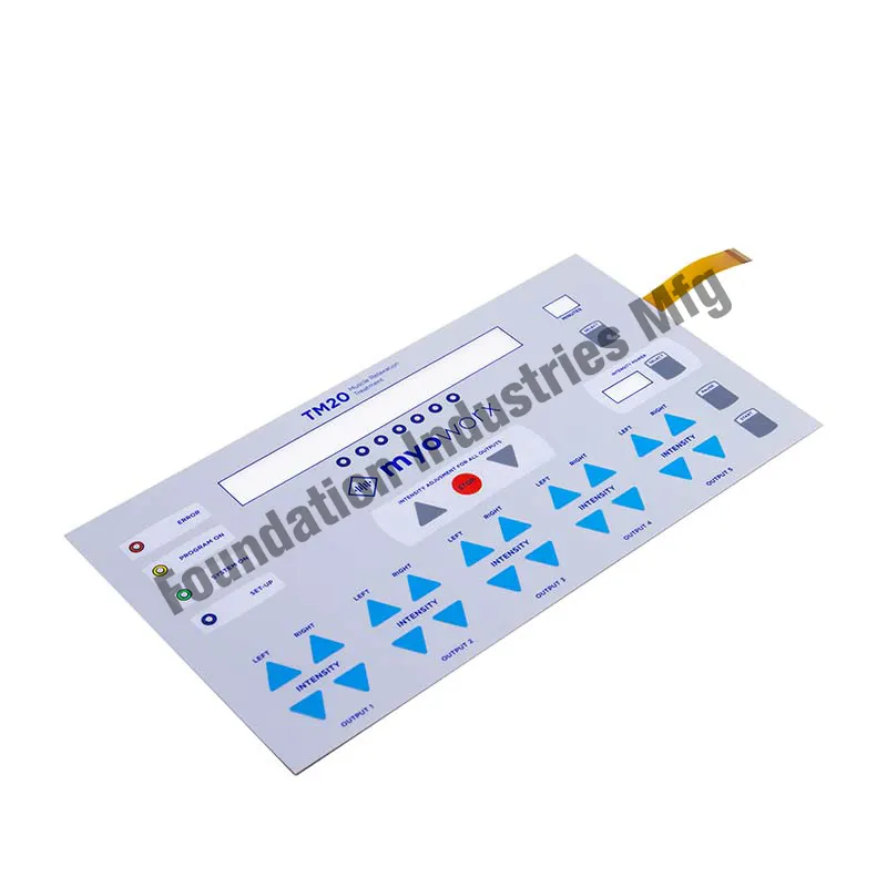
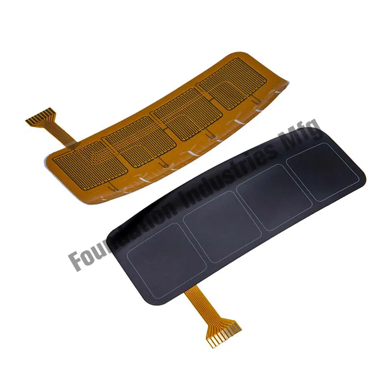
A custom membrane keypad switch is a type of input device that is used to control electronic devices and machines. It consists of a thin, flexible membrane that contains printed circuitry and tactile buttons or switches. When a button is pressed, the membrane flexes and makes contact with the circuitry, sending a signal to the device being controlled. Custom membrane keypad switches can be designed to meet specific needs and requirements, making them ideal for applications where precise control is required.

Here are some benefits of using a custom membrane keypad switch for better control:

Customization: Custom membrane keypad switches can be designed to meet specific requirements and needs. This means that the layout, size, shape, and color of the keypad can be customized to fit the application, making it easier to control the device or machine.

Durability: Membrane keypads are designed to be durable and long-lasting. They are resistant to moisture, dust, and other environmental factors that can damage traditional switches. This means that they can be used in harsh environments and applications without fear of failure.

Tactile feedback: Custom membrane keypad switches can be designed to provide tactile feedback when a button is pressed. This can help the user to know that the button has been activated, even in situations where visual feedback is not possible.

Ease of use: Membrane keypads are designed to be easy to use. membrane switches manufacturer The buttons are typically large and easy to press, and the layout of the keypad can be customized to fit the user’s needs. This makes it easier to control the device or machine, even in situations where the user is wearing gloves or is in a low-light environment.

Cost-effective: Custom membrane keypad switches are cost-effective compared to other types of input devices. They are made from inexpensive materials and can be manufactured in large quantities, making them an affordable option for many applications.

In conclusion, custom membrane keypad switches offer many benefits for better control of electronic devices and machines. They can be customized to meet specific needs and requirements, are durable and long-lasting, provide tactile feedback, are easy to use, and are cost-effective.

How do custom membrane keypad switches compare to other types of input devices?

Custom membrane keypad switches offer several advantages compared to other types of input devices.

Here are some comparisons between custom membrane keypad switches and other types of input devices:

Customization: Custom membrane keypad switches can be designed to meet specific needs and requirements, making them ideal for applications where precise control is required. In contrast, other input devices such as touchscreens or mechanical switches may not be as customizable.

Durability: Membrane keypads are designed to be durable and long-lasting. They are resistant to moisture, dust, and other environmental factors that can damage traditional switches. In contrast, other input devices such as mechanical switches may be more prone to damage from environmental factors.

Tactile feedback: Custom membrane keypad switches can be designed to provide tactile feedback when a button is pressed. This can help the user to know that the button has been activated, even in situations where visual feedback is not possible. In contrast, touchscreens may not provide tactile feedback, which can make it harder for the user to know that the input has been received.

Ease of use: Membrane keypads are designed to be easy to use. The buttons are typically large and easy to press, and the layout of the keypad can be customized to fit the user’s needs. This makes it easier to control the device or machine, even in situations where the user is wearing gloves or is in a low-light environment. In contrast, touchscreens may be less intuitive to use and may require more training.

Cost-effective: Custom membrane keypad switches are cost-effective compared to other types of input devices. They are made from inexpensive materials and can be manufactured in large quantities, making them an affordable option for many applications. In contrast, touchscreens and other input devices may be more expensive to manufacture and may require more maintenance.

Overall, custom membrane keypad switches offer many advantages compared to other types of input devices. They can be customized to meet specific needs, are durable and long-lasting, provide tactile feedback, are easy to use, and are cost-effective.

Categories: Default

Tags:

How can designers optimize membrane switches for specific applications?

Designers can optimize membrane switches for specific applications by considering the following factors:

Operating environment: The operating environment of the device is an important consideration when designing a membrane switch. The switch should be designed to withstand exposure to harsh environments, such as dust, moisture, and extreme temperatures. The materials and components used in the switch should be selected to provide the necessary level of durability and reliability for the specific operating environment.

Ergonomics: The ergonomics of the device should be considered when designing the membrane switch. The layout, shape, size, and sensitivity of the switches should be optimized to provide a comfortable and user-friendly interface for the user. The graphics and symbols on the switch should be clear and easy to read, providing a clear visual indication of each switch’s function.

Customization: The membrane switch should be customizable to meet the specific needs of the application. The layout, shape, size, sensitivity, and tactile feedback of the switches should be adjustable to fit the requirements of the device. The graphics and symbols on the switch should be customizable to provide a clear visual indication of each switch’s function.

Electrical requirements: The electrical requirements of the device should be considered when designing the membrane switch. The switch should be designed to provide the necessary level of electrical performance for the specific application. This may include considerations such as contact resistance, insulation resistance, and actuation force.

Cost-effectiveness: The membrane switch should be designed to be cost-effective for thespecific application. This may involve selecting materials and components that are cost-effective, designing the switch for ease of manufacture, and optimizing the layout and size of the switch to minimize material waste.

Regulatory requirements: The membrane switch should be designed to meet any regulatory requirements for the specific application. This may include considerations such as compliance with safety standards and electromagnetic compatibility (EMC) requirements.

User feedback: User feedback should be considered when designing the membrane switch. User testing and feedback can help identify areas where the switch can be improved to provide a better user experience.

Overall, designers can optimize membrane switches for specific applications by considering the operating environment, ergonomics, customization, electrical requirements, cost-effectiveness, regulatory requirements, and user feedback. By working with a supplier who specializes in custom membrane switches, waterproof membrane switch designers can create switches that are optimized for their unique requirements, helping to improve functionality, usability, and overall user experience.

What are some common safety standards and EMC requirements for membrane switches?

Safety standards and electromagnetic compatibility (EMC) requirements are important considerations when designing membrane switches for various applications.

Here are some of the most common safety standards and EMC requirements that designers should be aware of:

UL 94: UL 94 is a standard for safety of flammability of plastic materials for parts in devices and appliances. This standard measures the flame retardant properties of materials used in the membrane switch and ensures that they meet safety requirements.

RoHS: RoHS is a directive that restricts the use of certain hazardous materials in electrical and electronic equipment. The directive limits the use of substances such as lead, mercury, cadmium, and hexavalent chromium in the manufacture of membrane switches.

REACH: REACH is a regulation that addresses the production and use of chemical substances in the European Union. The regulation requires the registration, evaluation, authorization, and restriction of chemical substances used in products such as membrane switches.

IP Rating: The IP rating system is used to classify and rate the degree of protection provided by enclosures for electronic equipment. The rating system provides an indication of the level of protection against dust and moisture ingress, and can be used to ensure that membrane switches meet the required level of protection for the specific application.

EMC requirements: Electromagnetic compatibility (EMC) requirements are important considerations when designing membrane switches for applications that require reliable operation in the presence of electromagnetic fields. EMC requirements ensure that the membrane switch does not interfere withother electronic devices or systems in its vicinity, and that it is not susceptible to interference from other sources. Some common EMC requirements for membrane switches include:

Conducted emissions: Conducted emissions are unwanted electrical signals that are conducted through power and signal cables. EMC requirements typically specify limits on the level of conducted emissions that the membrane switch can produce.

Radiated emissions: Radiated emissions are unwanted electrical signals that are radiated into the environment. EMC requirements typically specify limits on the level of radiated emissions that the membrane switch can produce.

Immunity: Immunity refers to the ability of the membrane switch to operate properly in the presence of electromagnetic fields. EMC requirements typically specify the level of immunity required for the specific application, such as immunity to electrostatic discharge (ESD), radio frequency (RF) interference, and electromagnetic fields (EMF).

Overall, designers should be aware of the safety standards and EMC requirements that apply to their specific application when designing membrane switches. By working with a supplier who is knowledgeable about these requirements, designers can ensure that their membrane switches meet the necessary standards for safety and electromagnetic compatibility.

Categories: Default

Tags:

What are some common types of galvanized ring shank siding nails?

Some common types of galvanized ring shank siding nails include:

Casing nails

Typically used for attaching moldings and trim, casing nails have a small diameter head that sits flush with the surface. Lengths commonly range from 1 to 2 inches.

Face nails

These nails have a larger head that is intended to be exposed on the face of siding or trim materials. Face nails are usually between 1.5 to 3 inches long.

Siding nails

Specifically designed for fastening siding materials, siding nails have ringed shanks that grip into wood and resist withdrawal. Ring shanks start about 0.5 inches below the head. Lengths typically range from 1.25 to 3 inches.

Blind nails

Similar to siding nails but without an exposed head, blind nails are driven in at an angle so the head is concealed by siding panels. They have full length ring shanks. Common lengths are 1.5 to 3 inches.

Roofing nails

Used for attaching asphalt shingles and roofing felt, roofing nails have larger heads and are upward-tapered for easy driving into shingles. Lengths range from 0.75 to 2.5 inches.

The key differences between these types of galvanized ring shank nails are the head size and shape, length, and purpose. The ring shank provides resistance to withdrawal, making them a good choice for fastening siding and roofing materials that may be exposed to weather. Galvanizing protects against corrosion.

While these are common types, there are many variations and specialized nails available depending on the manufacturer and intended application.

Categories: Default

Check valve process

A check valve, also known as a non-return valve, is a mechanical device that allows fluid (gas or liquid) to flow through it in one direction only. It prevents the reverse flow of the fluid, ensuring that the process operates smoothly and safely. Check valves are commonly used in various industrial processes, water supply systems, and in many household appliances.

The process of a check valve can be broken down by china check valve factory into the following steps:

Inlet flow

Fluid enters the check valve through the inlet (or upstream) side. The pressure of the fluid pushes against the valve’s movable internal component, known as the closure member or disc.

Opening the valve

As the fluid pressure increases, it forces the closure member to open, allowing the fluid to flow through the valve. The design of the closure member can vary depending on the type of check valve (e.g., swing check valve, lift check valve, or ball check valve).

Flow direction

Fluid flows from the inlet side to the outlet (or downstream) side of the valve. The velocity and pressure of the fluid maintain the open position of the closure member, ensuring unobstructed flow.

Reverse flow prevention

If the fluid pressure on the outlet side becomes greater than the inlet side, the closure member is pushed back to its original position, blocking the reverse flow. This ensures that the fluid can only flow in one direction.

Closing the valve

When the fluid pressure equalizes or the flow stops, the closure member returns to its original position, sealing the valve. This prevents backflow and maintains the desired process conditions.

Categories: Default

How can I tell if the HITACHI EX35 idler needs replacement?

Excessive wear

Check the idler wheel for signs of heavy abrasion, grooving or flat spots. Worn down idlers will not support the track properly, reducing traction and stability. Idlers that are 1/2 inch or more narrower than new ones should be replaced.

Cracking or damage

Inspect the idler for any cracks in the rubber compound or damage to metal cores/spindles. Structural failure compromises the idler’s ability to support and guide the track.

Loose components

Ensure all bolts and nuts securing the idler to the idler frame are tight. Loose hardware can lead to idler misalignment and premature replacement need.

Noise

Excessive squealing, grinding or rattling noises when the excavator is moving can indicate a failing idler. Worn out idlers often cause more noise.

Visible separation

Check for any visible cracks forming between the two halves of split idlers or separation between the rubber and metal on segmented spindles. Complete separation would immobilize the track.

Difficulty moving tracks

If pushing one track control lever becomes noticeably more difficult than the other side, it likely means an idler is failing to cradle and support the track properly.

Safety issue

If the condition of an idler raises concerns over stability, traction or control, it should be replaced immediately regardless of hours of use. Safety should not be compromised.

Some factors that accelerate idler wear and replacement on Hitachi EX35 excavators include:

Excessive load

Frequently handling heavy loads at the limit of the excavator’s capacity rating will put more stress on all undercarriage components including the idlers.

Harsh operations

Activities such as constant switching between carry, travel and dig with an overloaded bucket require more work from the undercarriage and will wear out idlers faster.

Severe conditions

Operating in abrasive, wet or corrosive environments exposes the undercarriage and idlers to more damage and accelerated deterioration.

Inadequate lubrication

Lack of lubrication is probably the fastest way to damage Hitachi EX35 idlers

and other undercarriage parts. Stick to the recommended lubrication schedules.

Old idler

Replacing worn out idlers earlier will help prevent further damage to adjacent components like tracks, rollers, sprockets etc. If in doubt, it is best to replace idlers on the early side.

Categories: Default

How can I customize a nonwoven tote bag with my own design or logo?

Customizing a nonwoven tote bag with your own design or logo is a great way to promote your brand or event. Here are the steps to follow:

Choose a supplier

Look for a reputable supplier that offers nonwoven tote bags use polypropylene nonwoven fabric and customization services. Make sure to check their quality standards and minimum order quantity requirements.

Choose the bag style and color

Decide on the style and color of the bag that will work best for your design. Nonwoven tote bags come in different sizes, shapes, and colors.

Create your design

Using graphic design software or hiring a designer, create a design that represents your brand or event. Make sure the design is high resolution and can be scaled to fit the bag size.

Submit your design to the supplier

Once your design is ready, submit it to the supplier along with your order details. They will provide you with a proof of the design and ask for your approval before printing.

Receive your customized bags

Once you approve the design proof, the supplier will print your design onto the nonwoven tote bags and ship them to you.

Customizing a nonwoven tote bag is a great way to create brand awareness and promote sustainability at the same time.

Categories: Default

What are the different types of fire water monitor

There are several types of fire water monitor, each designed for specific firefighting applications. Here are some of the most common types of fire water monitors:

Fixed water monitors

Fixed water monitors are permanently mounted on a structure or a vehicle and are used for stationary firefighting applications, such as protecting industrial facilities or loading docks.

Portable water monitors

Portable water monitors are designed to be carried by firefighters and can be quickly deployed to suppress fires in areas where fixed monitors are not available or accessible.

Elevated water monitors

Elevated water monitors are mounted on elevated platforms, such as firefighting aerial ladders or platforms, and can be used to suppress fires in high-rise buildings or other tall structures.

Oscillating water monitors

Oscillating water monitors are designed to move back and forth, providing a wider coverage area than fixed monitors.

Dual-agent monitors

Dual-agent monitors are designed to deliver a combination of water and foam or other firefighting agents to suppress fires more effectively.

Remote-controlled water monitors

Remote-controlled water monitors are operated by a firefighter using a joystick or a remote control device, allowing them to be operated from a safe distance.

Deck water monitors

Deck water monitors are designed for marine firefighting applications and are used to suppress fires on ships or offshore platforms.

The choice of fire water monitor will depend on the specific requirements of the firefighting application and the environment in which it will be used. Firefighters must select the appropriate type of fire water monitor to ensure effective fire suppression and safety.

Categories: Default

How can I determine the correct valve size for my piping system?

Determining the correct size for a swing check valve for your piping system requires careful consideration of several factors. Here are some steps you can take to determine the correct valve size:

Determine the maximum flow rate

The first step in selecting the correct valve size is to determine the maximum flow rate that the valve will need to accommodate. This can be determined based on the size and length of the piping system and the maximum flow rate of the fluid or gas that will be flowing through the system.

Calculate the required valve size

Once you have determined the maximum flow rate, you can calculate the required valve size using industry-standard formulas or software. The required valve size will depend on factors such as the flow rate, the pressure drop across the valve, and the valve’s Cv (flow coefficient).

Select the closest valve size

Once you have calculated the required valve size, you can select the closest valve size that is available in the market. It is generally recommended to select a valve that is slightly larger than the calculated size to ensure that the valve can accommodate any changes in the flow rate or pressure drop over time.

Verify compatibility

Before installing the valve, it is important to verify that the selected valve size is compatible with the piping system and other components, such as pumps and other valves.

It is important to consult with a qualified engineer or China swing check valve suppliers to determine the correct valve size for your specific piping system to ensure reliable and safe operation. They can also provide guidance on industry-standard formulas or software that can be used to calculate the required valve size.

Categories: Default

mechanical structural steel

This type of steel refers to alloy steels suitable for the manufacture of machines and mechanical parts. It is based on high-quality carbon turbulent steel, and one or several alloying elements are properly added to improve the strength, toughness and hardenability of the steel. This type of steel is usually used after heat treatment (such as quenching and tempering treatment, surface hardening treatment). It mainly includes two categories of commonly used alloy structural steel and alloy spring steel, including quenched and tempered alloy steel, surface hardened alloy steel (carburizing steel, nitrided steel, surface high-frequency quenching steel, etc.), cold plastic forming Use alloy steel (steel for cold upset forging, steel for cold extrusion, etc.). According to the basic composition series of chemical composition, it can be divided into Mn series steel, SiMn series steel, Cr series steel, CrMo series steel, CrNiMo series steel, Nj series steel, B series steel, etc.

Alloy structural steel

The carbon content wc of alloy structural steel is lower than that of carbon structural steel, generally in the range of 0.15% to 0.50%. In addition to carbon, it also contains one or several alloying elements, such as silicon, manganese, vanadium, titanium, boron and nickel, chromium, molybdenum, etc.
Alloy structural steel is easy to harden and not easily deformed or cracked, and it is convenient for heat treatment to improve the performance of the steel.
Alloy structural steel is widely used in the manufacture of various transmission parts and fasteners for automobiles, tractors, ships, steam turbines, and heavy machine tools. Low carbon alloy steel is generally carburized, and medium carbon alloy steel is generally quenched and tempered.

alloy tool steel

Alloy tool steel is medium and high carbon steel containing a variety of alloying elements, such as silicon, chromium, tungsten, molybdenum, vanadium, etc. Alloy tool steel is easy to harden, not easy to deform and crack, and is suitable for making cutting tools, molds and measuring tools with large size and complex shape.
For different purposes, the carbon content of alloy tool steel is also different. The carbon content wc of most alloy tool steels is 0.5% to 1.5%. Steel for hot deformation molds has low carbon content, wc is in the range of 0.3% to 0.6%; steel for cutting tools generally contains about 1% carbon wc; steel for cold working molds has higher carbon content, such as graphite mold steel carbon content wc Up to 1.5%, the carbon content wc of high-carbon and high-chromium cold-working mold steel is as high as 2%.

High speed tool steel

High-speed tool steel is a high-carbon high-alloy tool steel. The carbon content wc in the steel is 0.7%-1.4%. The steel contains alloying elements that can form high-hardness carbides, such as tungsten, molybdenum, chromium, and vanadium.
High-speed tool steel has high red hardness. Under high-speed cutting conditions, the hardness does not decrease even when the temperature is as high as 500-600 degrees Celsius, thus ensuring good cutting performance.

Categories: Default

6 Tips For Using 4 way cross pipe fitting in Your Factory

Using 4 way cross pipe fittings in your factory can be a great way to create customized and efficient pipe systems.

Here are six tips for using 4 way cross pipe fittings effectively:

  1. Plan the layout: Before installing any 4 way cross pipe fittings, plan out the layout of your pipe system. Consider factors such as the size and shape of the space, the type of materials being transported, and the flow rate required.
  2. Choose the right size and material: Select 4 way cross pipe fittings that are the right size and material for your specific needs. Consider factors such as the temperature, pressure, and chemical resistance required.
  3. Use compatible fittings and pipes: Make sure that all pipe fittings and pipes are compatible with each other to ensure a leak-free and efficient system.
  4. Use appropriate tools: Use appropriate tools, such as a pipe cutter or hacksaw, to cut pipes to the appropriate length and remove any burrs or rough edges.
  5. Use pipe clamps or supports: Use pipe clamps or supports to secure pipes in place and prevent movement or damage over time.
  6. Regularly inspect and maintain the system: Regularly inspect and maintain the pipe system to ensure that all fittings and pipes are in good condition and functioning properly. This can help prevent leaks, damage, or other issues that can cause downtime or safety hazards.

By following these tips, you can effectively use 4 way cross pipe fittings to create a customized and efficient pipe system in your factory.

The Basics of 4 way cross pipe fitting You Need to Know

A 4 way cross pipe fitting is a type of plumbing fitting used to connect four pipes at right angles. Here are some basics of 4 way cross pipe fitting that you need to know:

  1. Types of materials: 4 way cross pipe fittings can be made from a variety of materials, including brass, stainless steel, PVC, and copper. The choice of material depends on the specific application and the requirements for temperature, pressure, and chemical resistance.
  2. Sizes: 4 way cross pipe fittings come in a range of sizes to accommodate different pipe sizes and flow rates. It is important to choose the right size fitting for the pipes being connected to ensure a secure and leak-free connection.
  3. Installation: 4 way cross pipe fittings are installed by cutting the pipes 4 way cross pipe fitting supplier to the appropriate length and inserting them into the fitting. The pipes are secured in place using clamps or other types of fittings.
  4. Functionality: 4 way cross pipe fittings allow four pipes to be connected at right angles, allowing fluid or gas to flow in four different directions. This makes them a versatile and efficient option for a variety of plumbing and piping applications.
  5. Compatibility: It is important to ensure that all pipes and fittings are compatible with each other to ensure a secure and leak-free connection. It is also important to use the appropriate tools and techniques for cutting and joining pipes to prevent damage or leaks.

Overall, 4 way cross pipe fittings are a versatile and efficient option for connecting four pipes at right angles. By choosing the right size and material, and ensuring proper installation and compatibility, these fittings can provide a secure and leak-free connection for a variety of plumbing and piping applications.

Categories: Default

Tags: